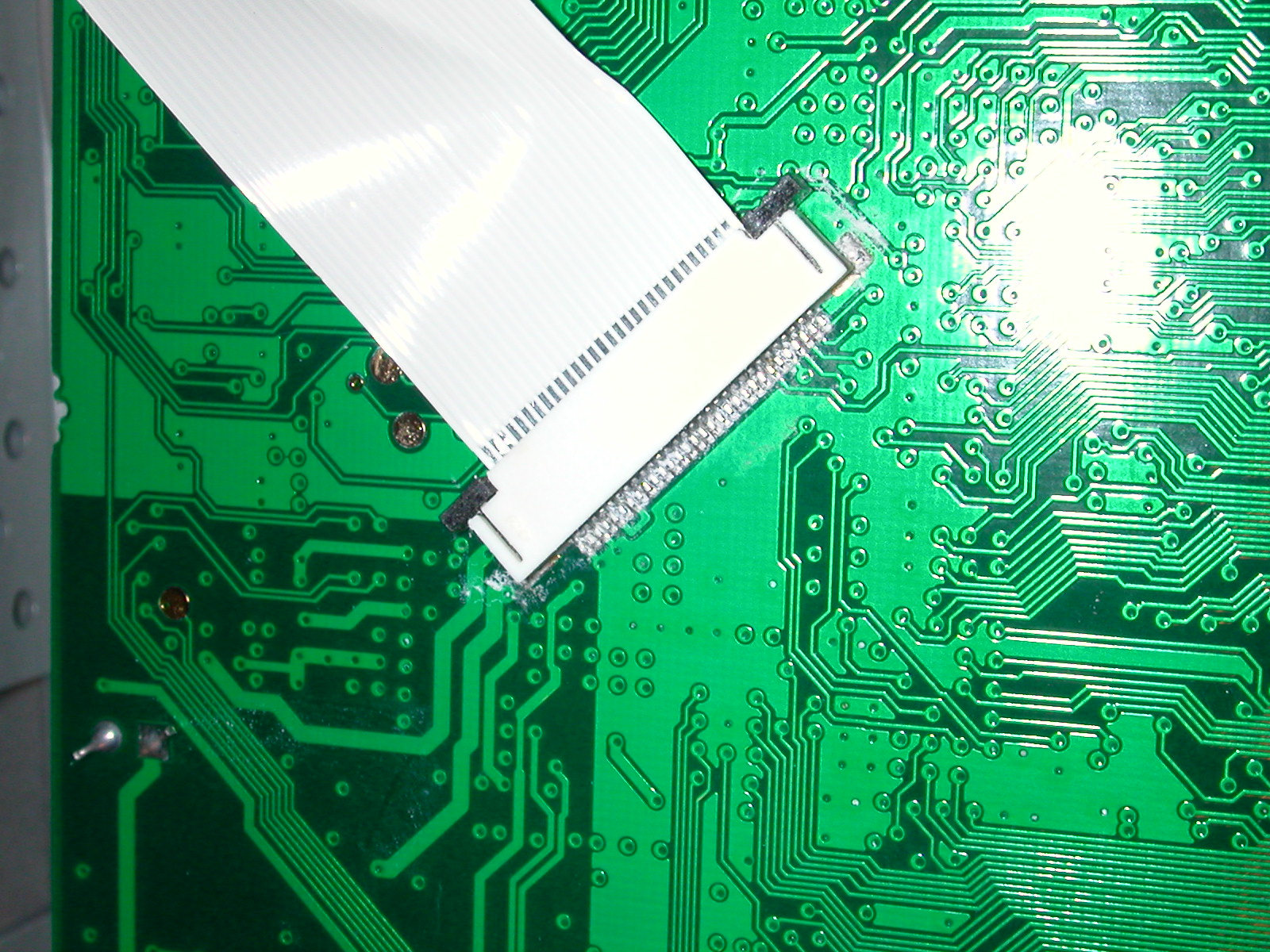
Adding a JTAG cable to the Livebox requires opening the box and use of a soldering iron. There are a couple of options depending on how good you are with the soldering iron. Adding discrete cables is easier than using the available connector but not quite as neat inside the box. There is information here on the PCB connection points for discrete cabling as well as some information on using JTAG on the Livebox. If you are going to add a connector, the pinout is here.
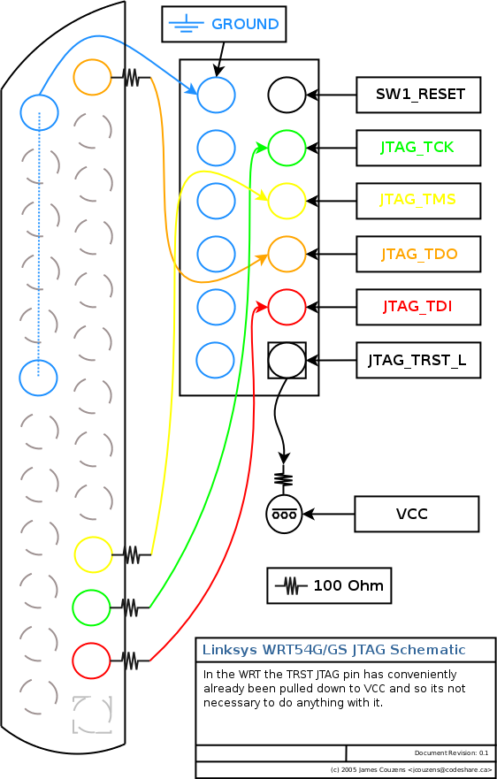
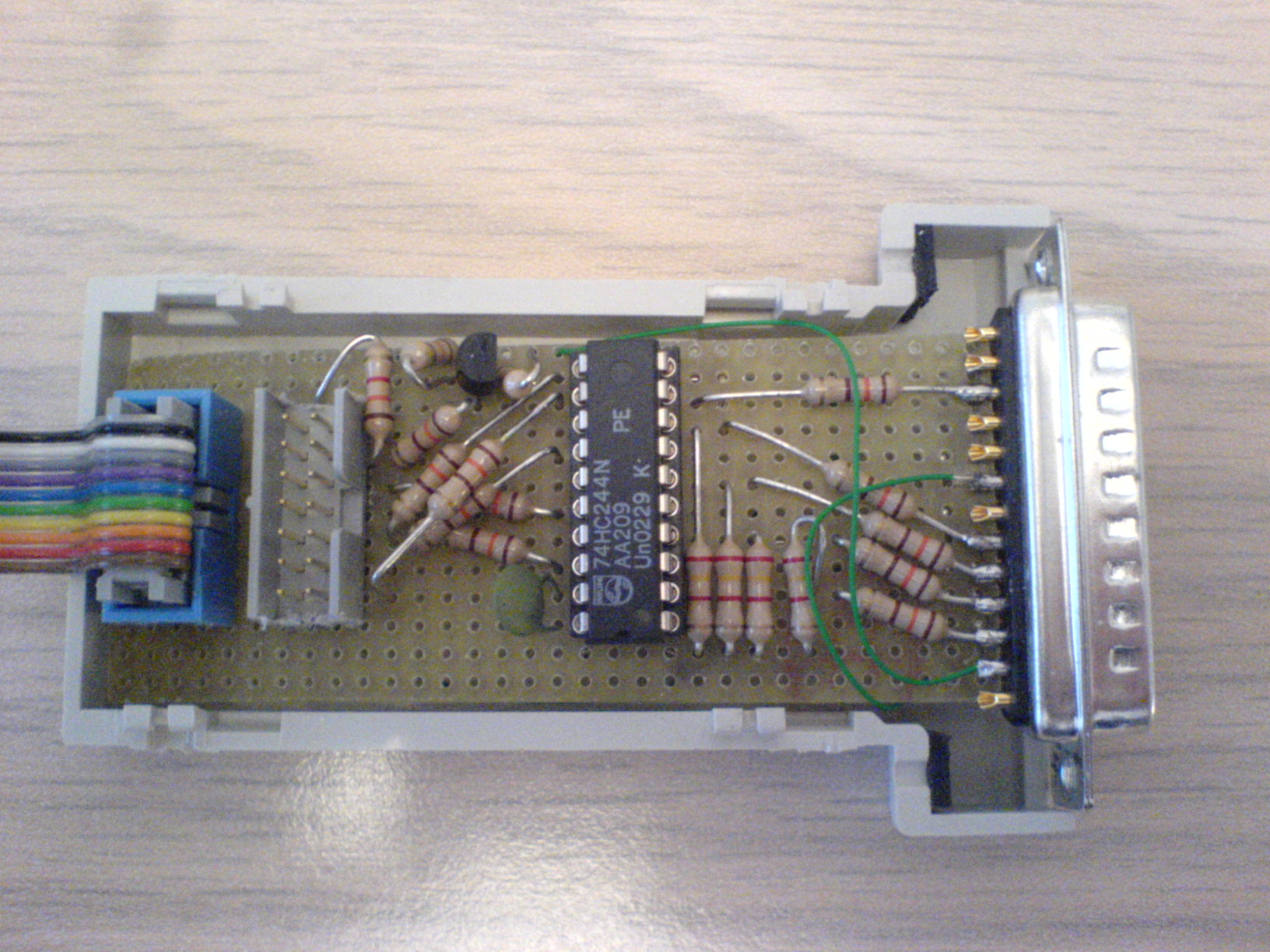
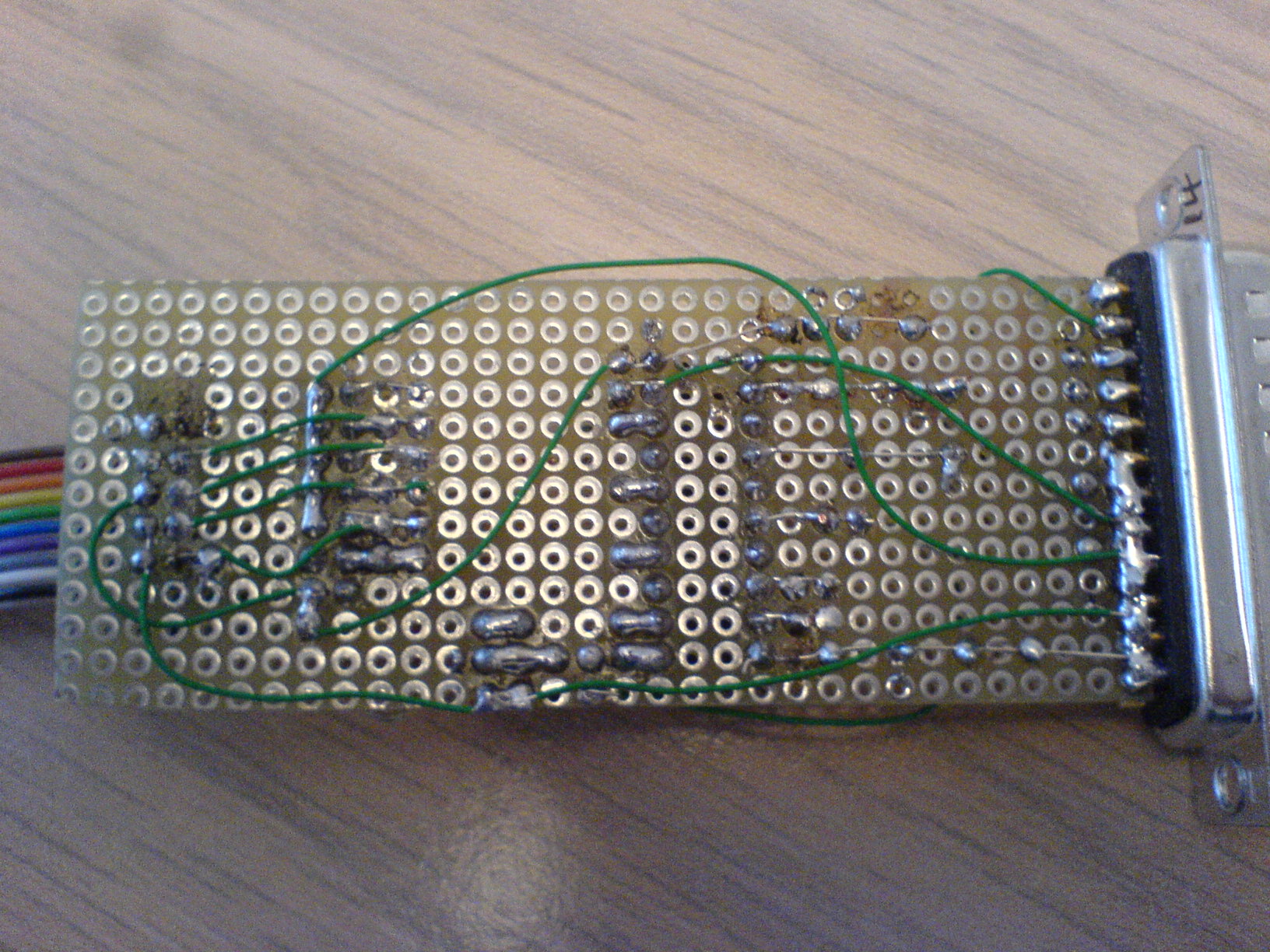
There are numerous schematics available for a standard JTAG adapter cable, based either on either Wiggler compatible or Xilinx compatible designs (the pinout differs between them so you need to decide which one to build, also some are passive cables using only resistors while others are active and use IC's, normally 74HC125's). I built both styles of cables using active parts but now only have a Wiggler cable which works perfectly.
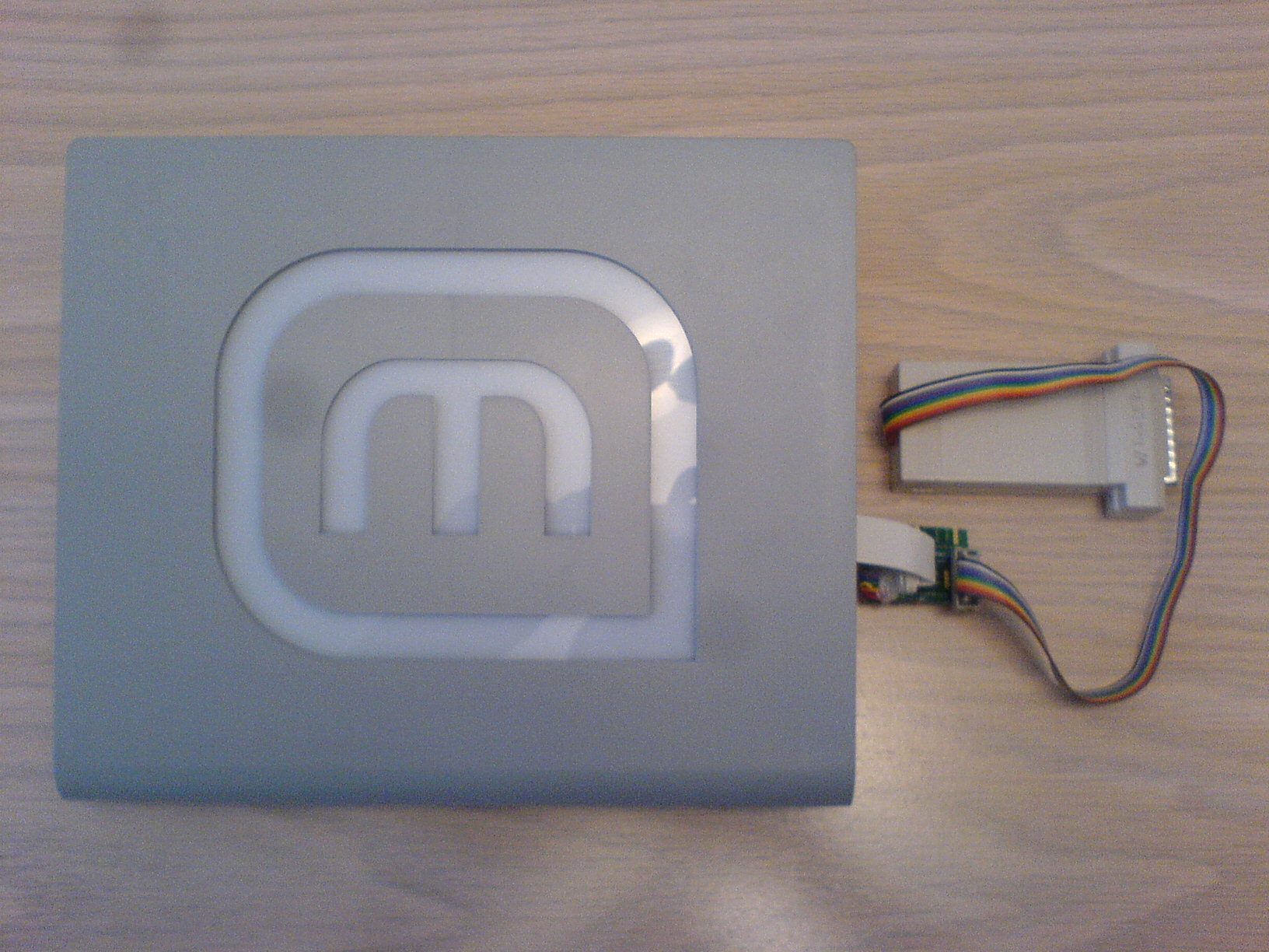
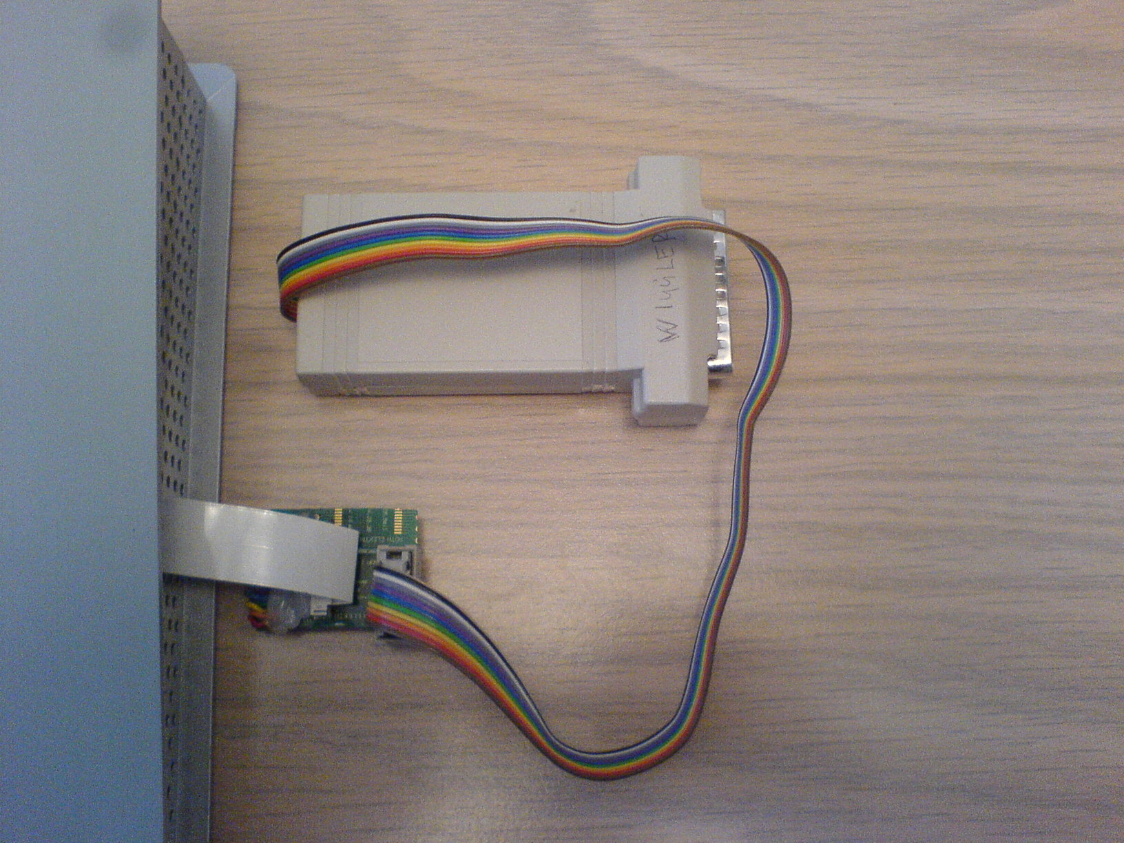
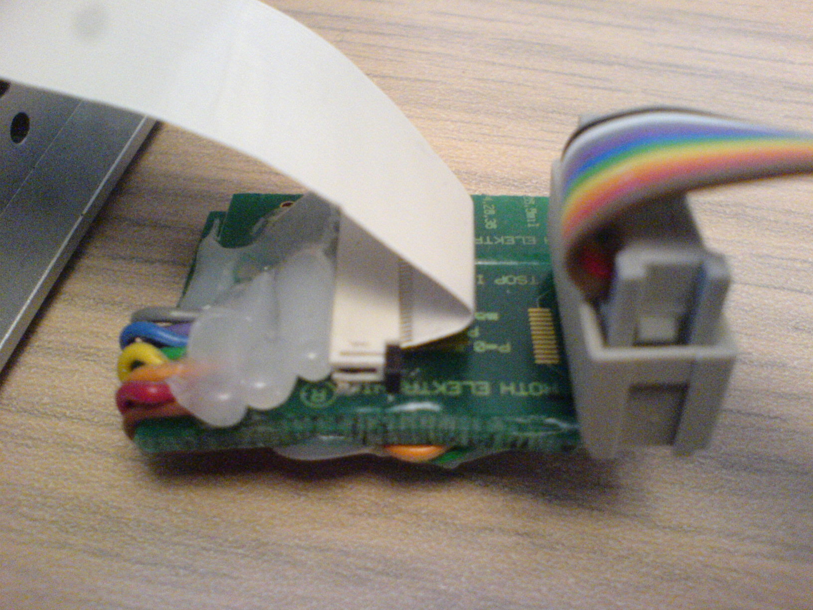
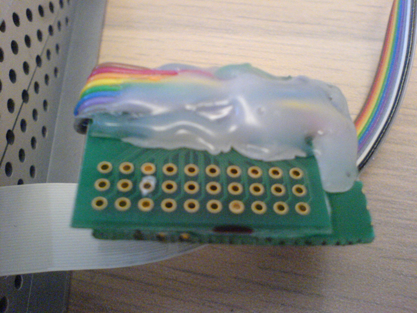
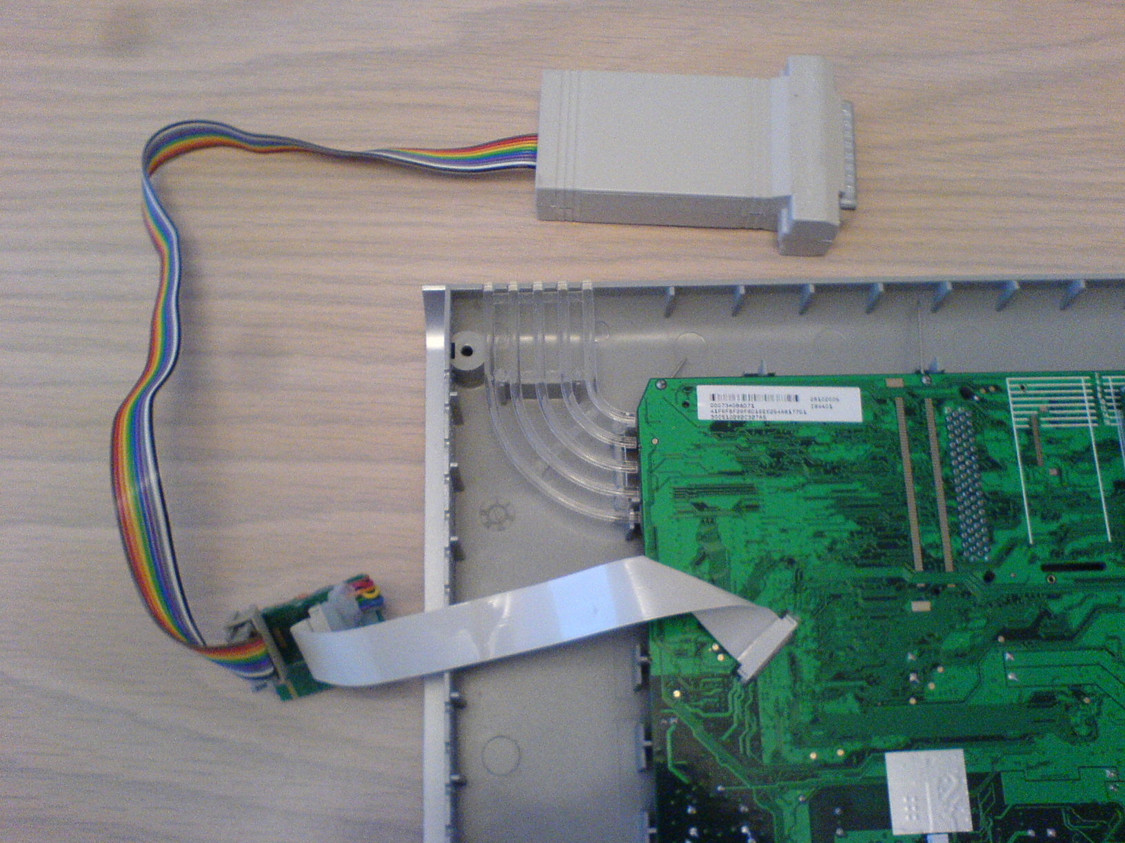
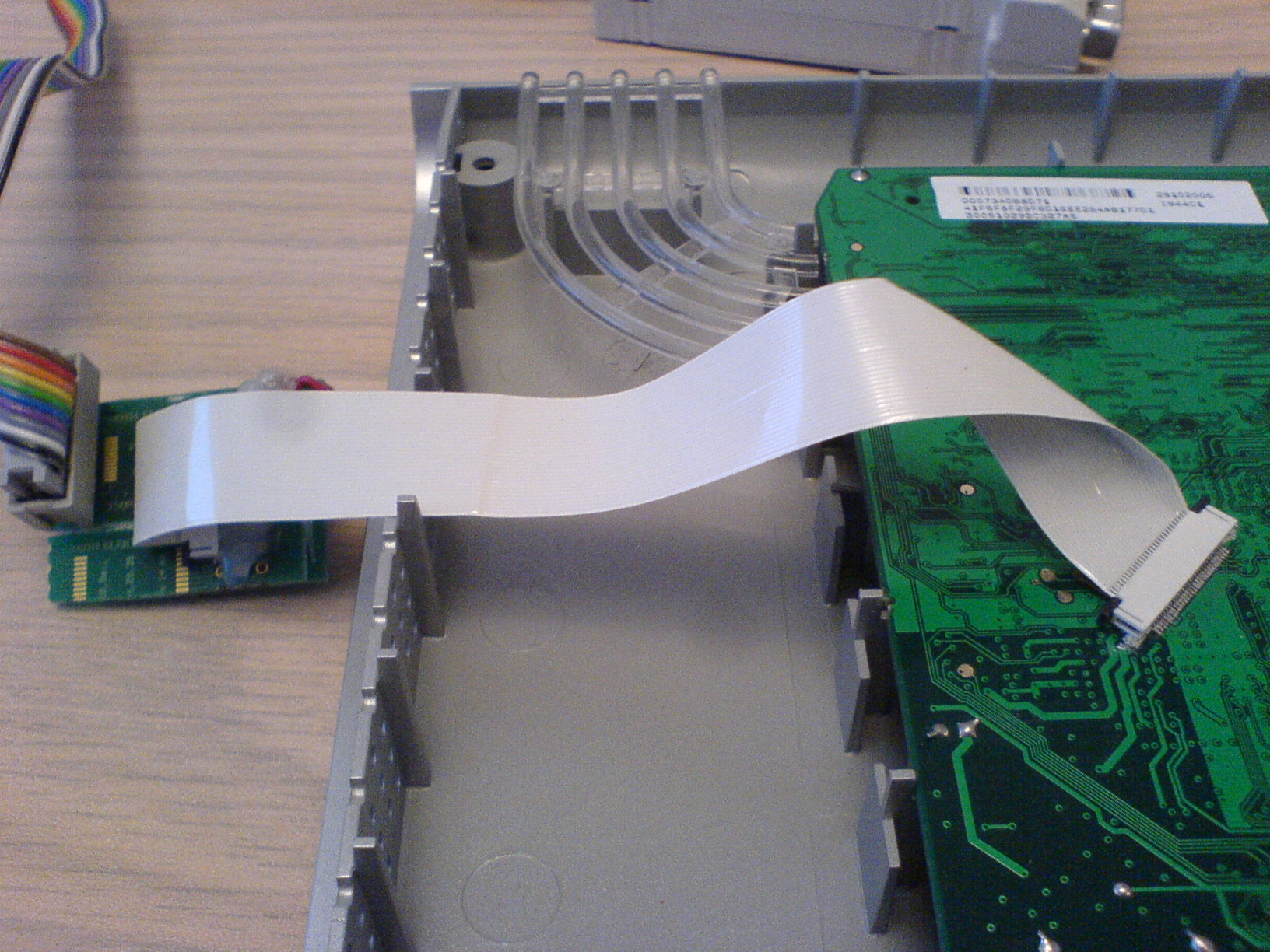
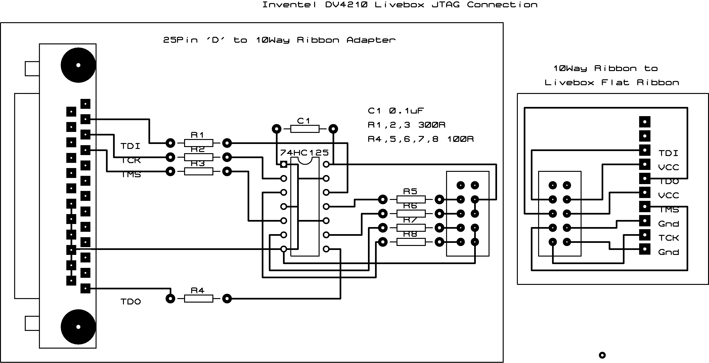
I used the connector and cable method so I could build a single active JTAG adapter but use it on multiple Liveboxes as well as on my BT Home Hub just by unplugging the cable and connecting it to another adapter. The following pictures show the method I used along with the schematic I used. The schematic shows the two adapters, one (Wiggler) is plugged into the parallel port and the other converts the 10 way ribbon cable from this adapter to the 30way flat connector on the livebox.
542-6693 0.5 FPC ZIF R/A SMT 30W T, Molex Part Number 52435-3072

458-9153 30 Way FFC Cable Assembly 0.5A 50V 0.5mm, Molex Part Number 98266-0325
The original HairyDairyMaid JTAG program did not work with the Wiggler pinout due to a minor bug in the code. This patch fixes that, but this version I modified for the Livebox also fixes the issue with byte swapping as well as supporting the various Livebox partitions for backup and flashing.
Once the cabling has been built and attached between the Livebox and the PC (please note the PC has to have a proper parallel port, a USB to Parallel adapter has issues and probably will NOT work due to the method of parallel port access required) you need to build and run the software. When running under Linux, ensure that the kernel has been built with the parallel port driver configured as a module as you need to unload the lp driver and load the ppdev driver. See the file B4U_Debrick.txt for details on this and the file backup.sh for the command lines I used to backup a Livebox with correct endianess. Writing to flash is very similar but you must ensure that the /nodma flag is used.