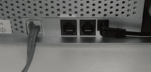
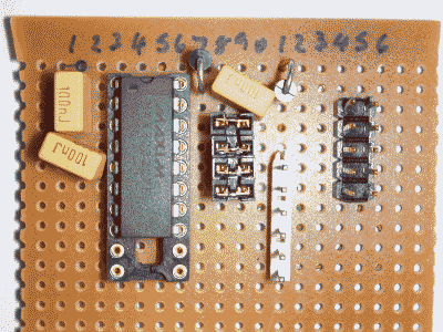
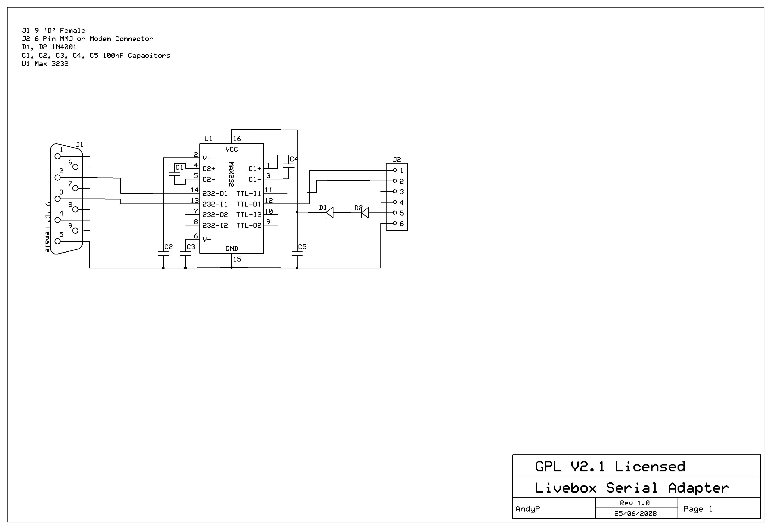
The component list is as follows, all parts should be available from any component store. The serial port is located under a tamperproof label next to the RJ11 connectors.
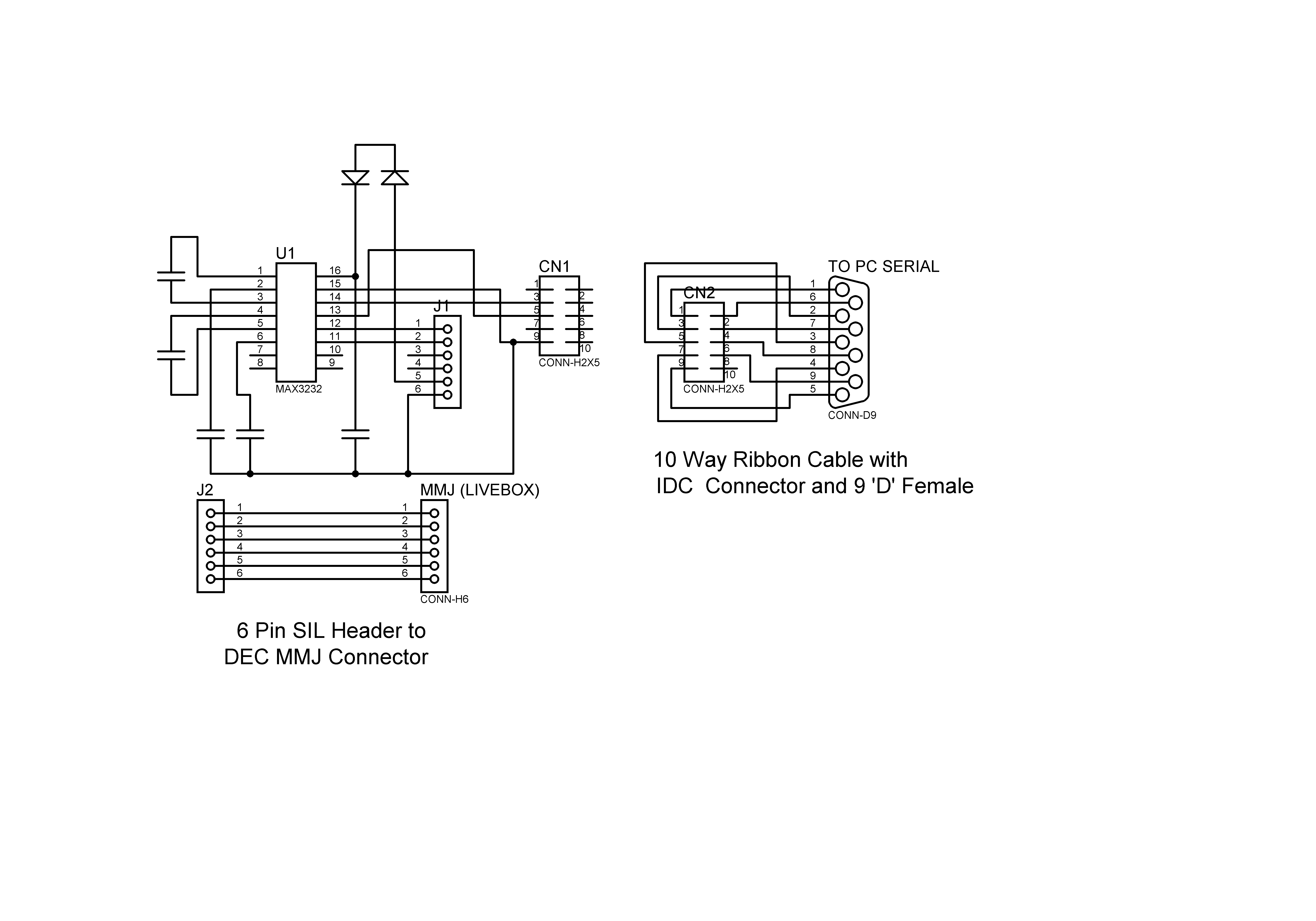
On my layout I have included 4 shorting links. These can be replaced by wire links as they were only used to easily change the pinout of the Tx/Rx lines on the cables during testing as I wasn't sure if the serial cable that I had was null modem or straight through and there was some confusion as to the pinout on the Livebox serial port.
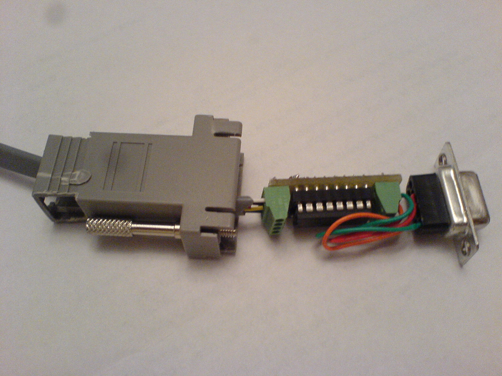
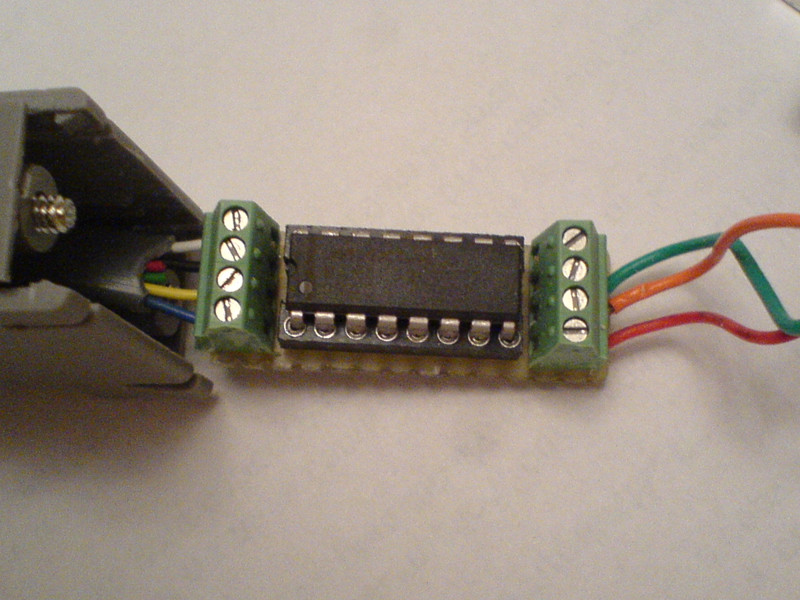
The diodes are used to drop the 5V supplied by the serial port to 3.5 volts for the MAX3232 so that the outputs from the MAX3232 to the BCM6348 are at 3.5 volts as it appears that this is the voltage the BCM6348 is running from.
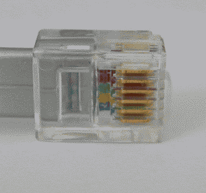
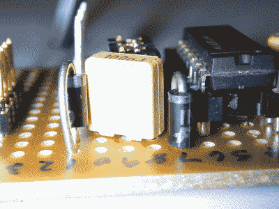
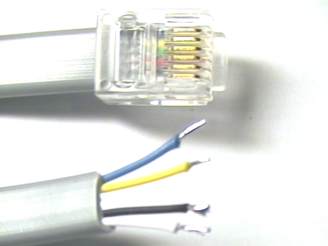
The MMJ cable was cut in half and only 1 end was used. If you do the same , verify that the colour coding of the cable end agrees with the connector on the veroboard.
Parameters for connection are 115200 Baud, No Parity , 8 Data Bits , 1 Stop Bit. When powering up the Livebox you should see the boot messages from the RedBoot bootloader and the Linux kernel before being requested for a username and password to login with.
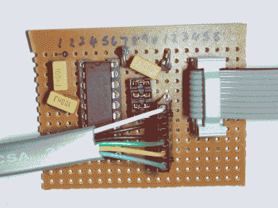
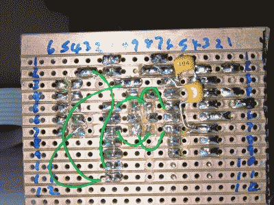
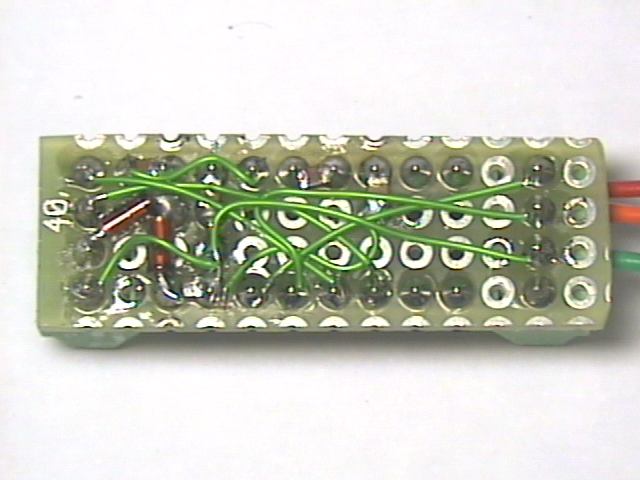
Serial Port Schematic V1.0 The Veroboard fits inside a small plastic box.
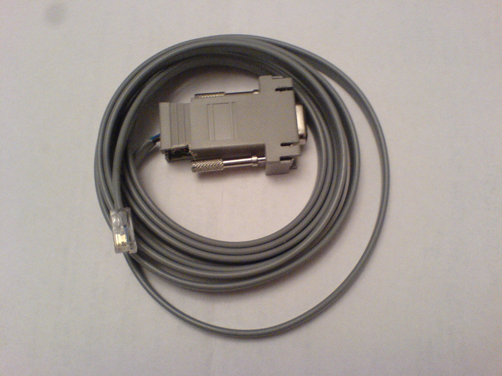
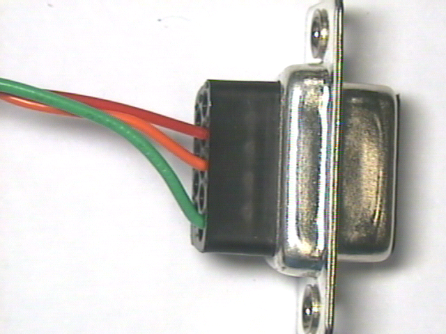
Serial Port Schematic V2.0 This now fits inside an 9 Pin Female 'D' Connector to RJ11 shell